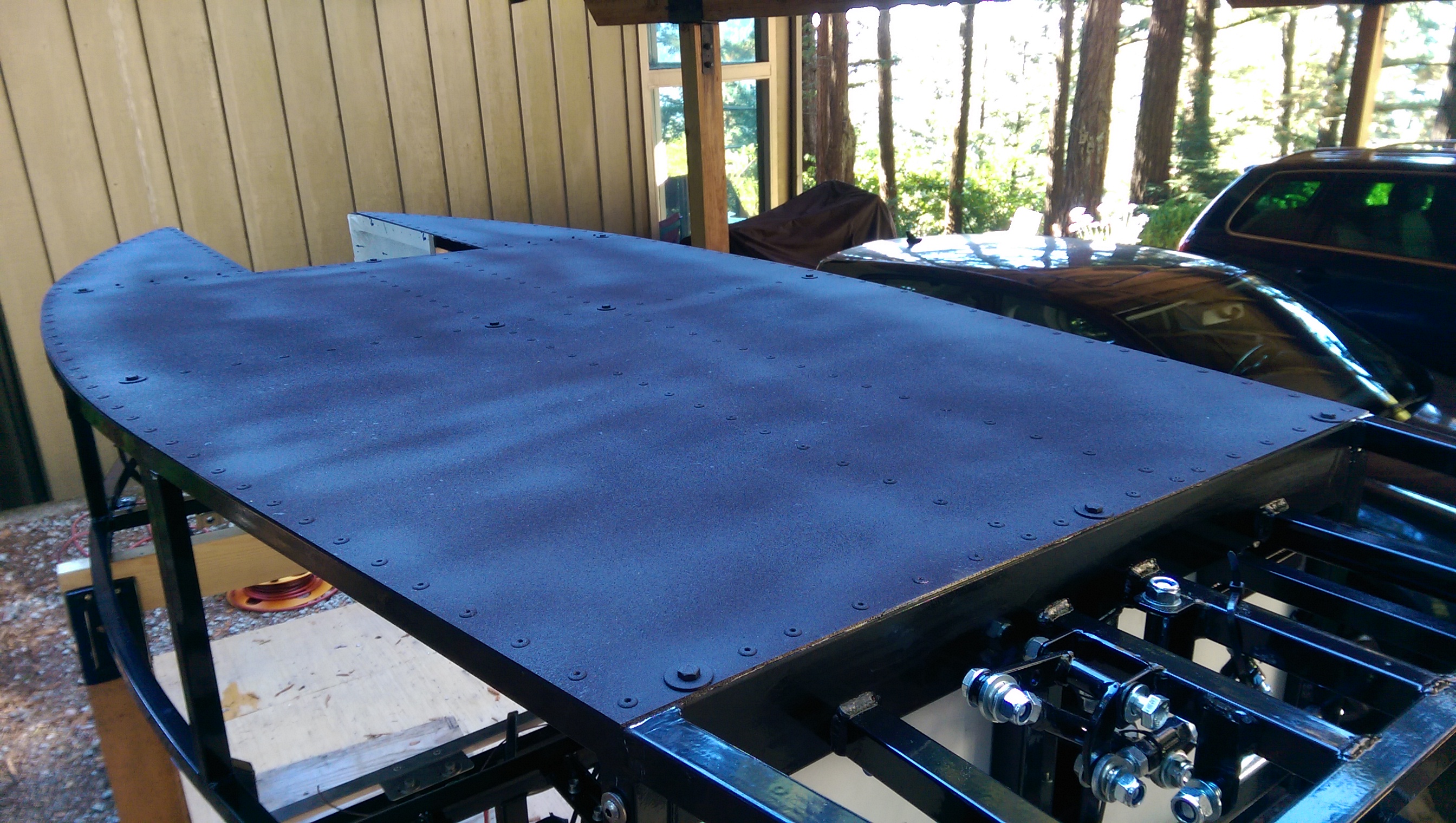
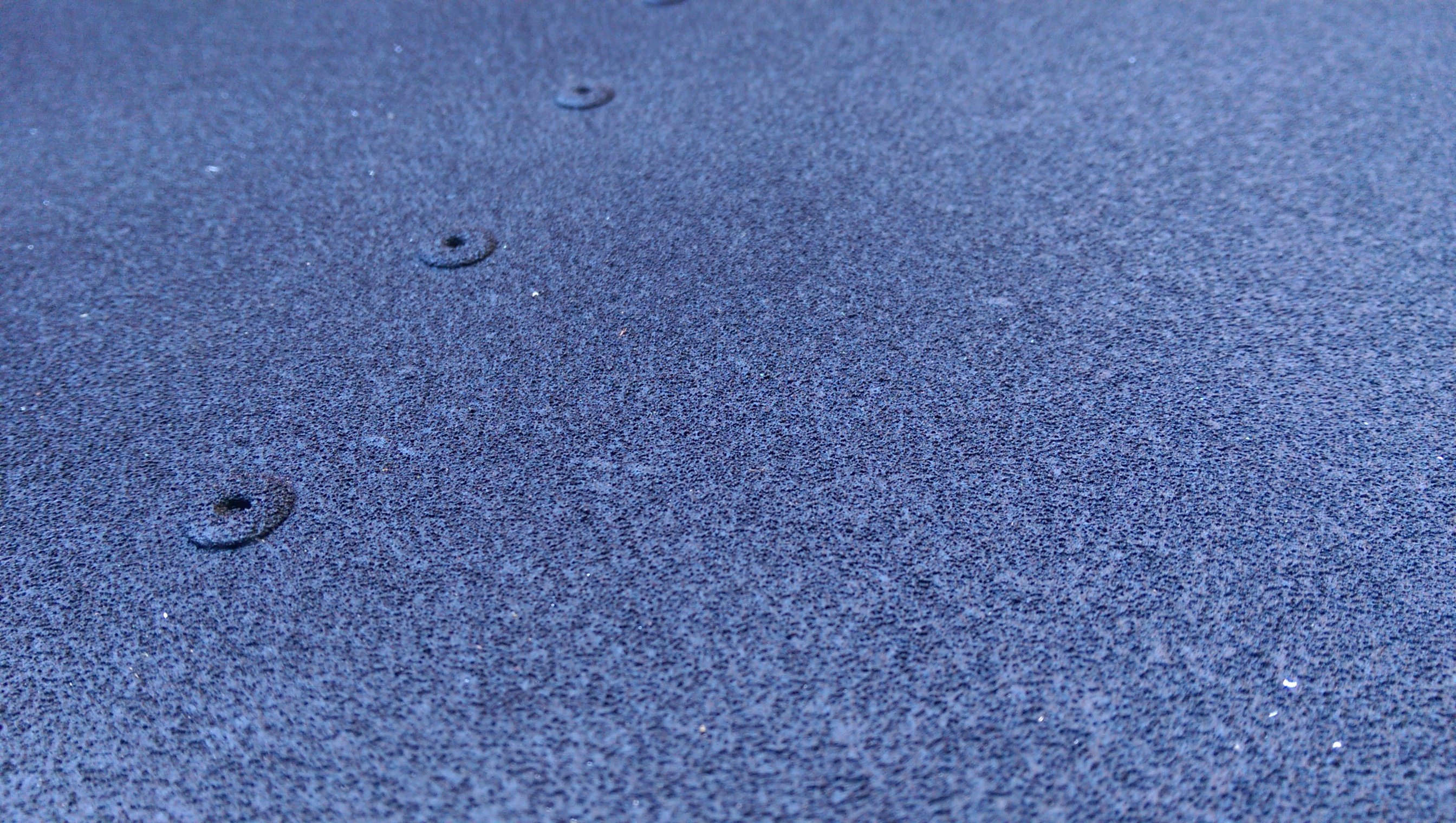
Before we flip her back over, took a swing at using Duplicolor rubberized undercoat to help deaden sound of pebbles and rocks bouncing off the underside. Not bad for aerosol can application. I may use this in the rear wheel area as well.
What could possibly go wrong?
Before we flip her back over, took a swing at using Duplicolor rubberized undercoat to help deaden sound of pebbles and rocks bouncing off the underside. Not bad for aerosol can application. I may use this in the rear wheel area as well.
So we righted the ship, and the assembly process can begin.
In effect, you will need to disassemble nearly the entire chassis – if only to finish the panels and/or remove the plastic backings that coat the aluminum from the laser cutter.
Further, I live in a high moisture environment, and am concerned about oxidation of the aluminum panels – so my goal is to methodically ensure that any panels that are exposed to moisture get treatment.
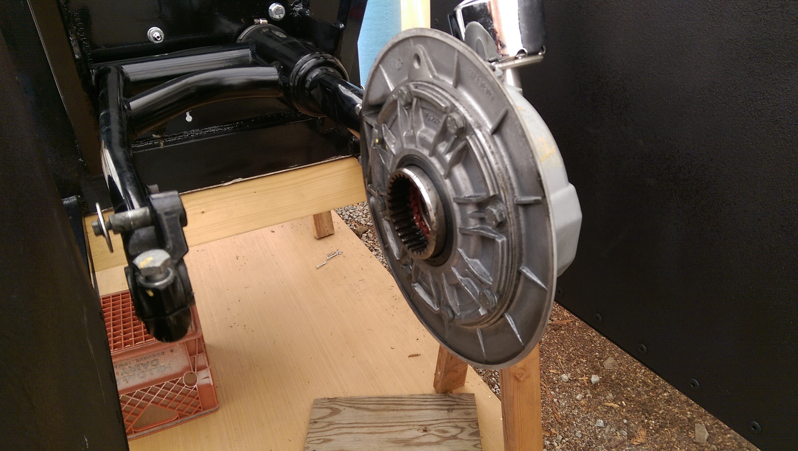
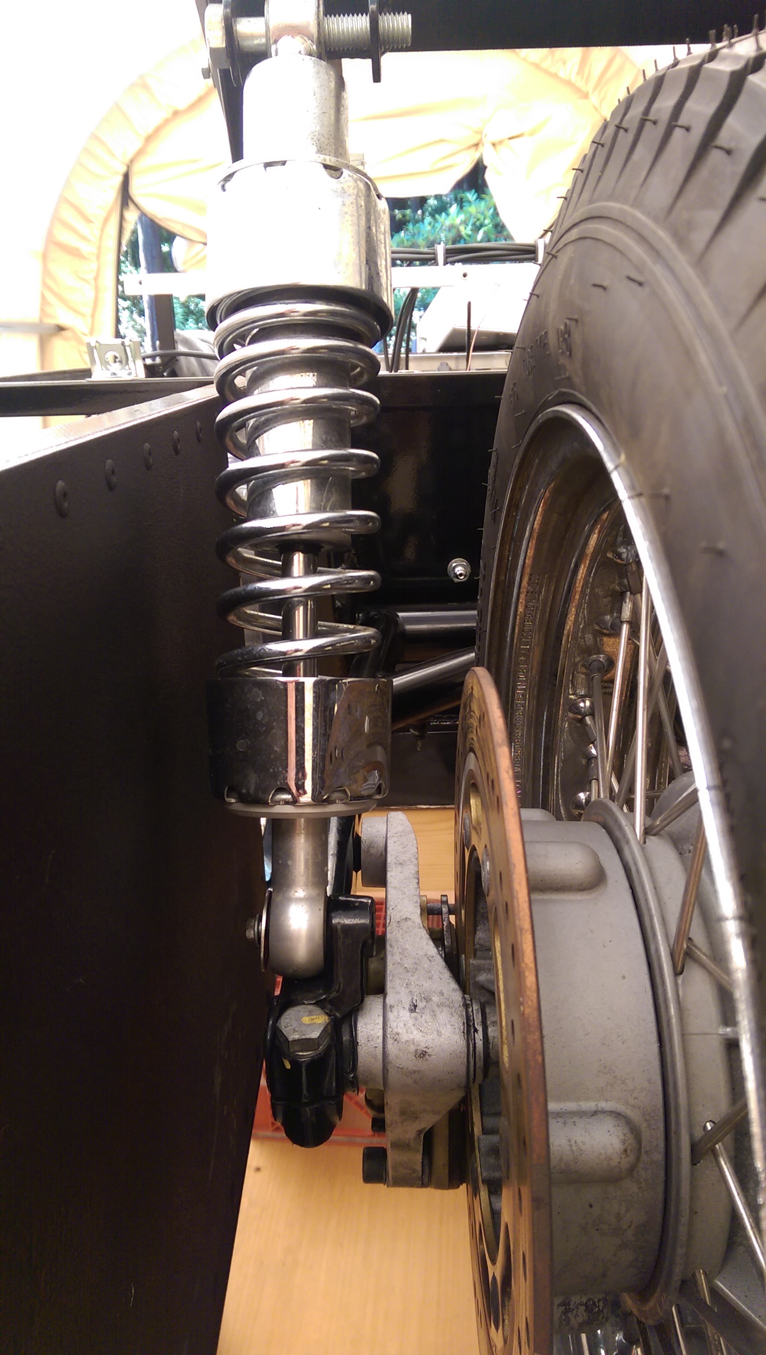
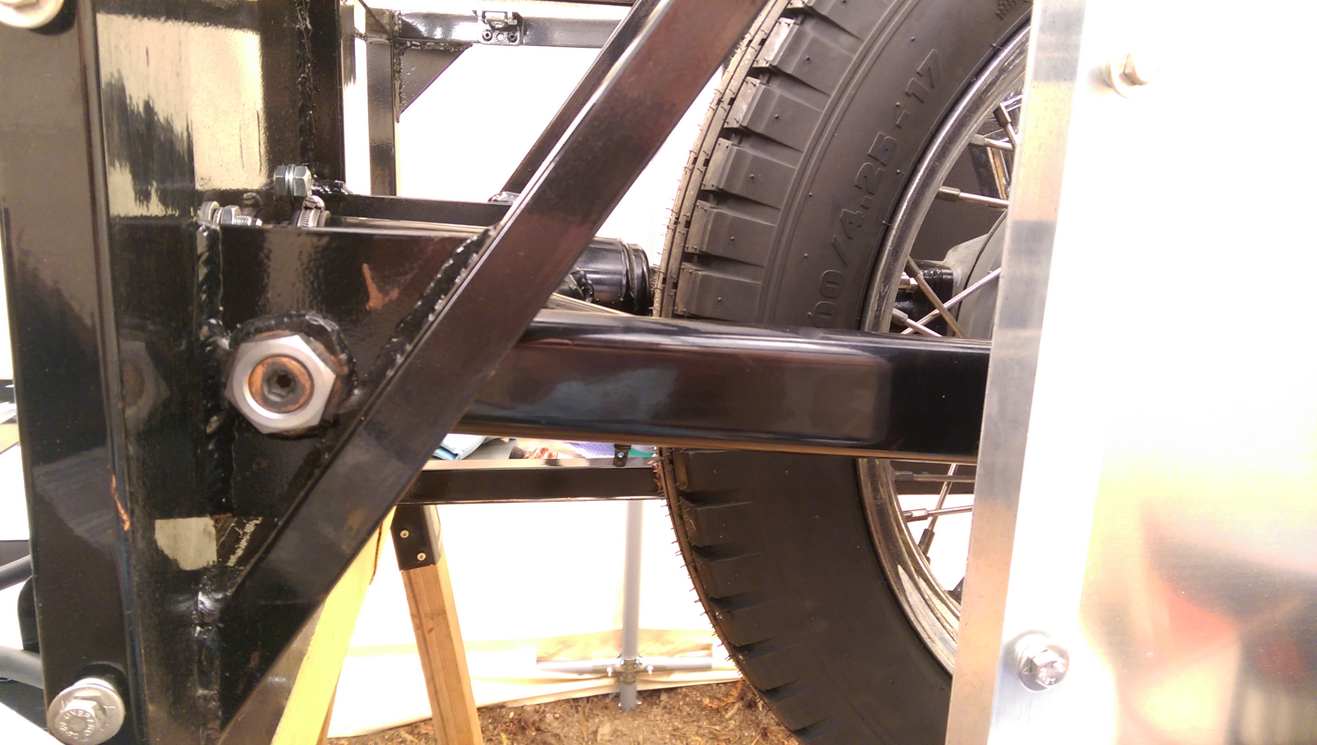
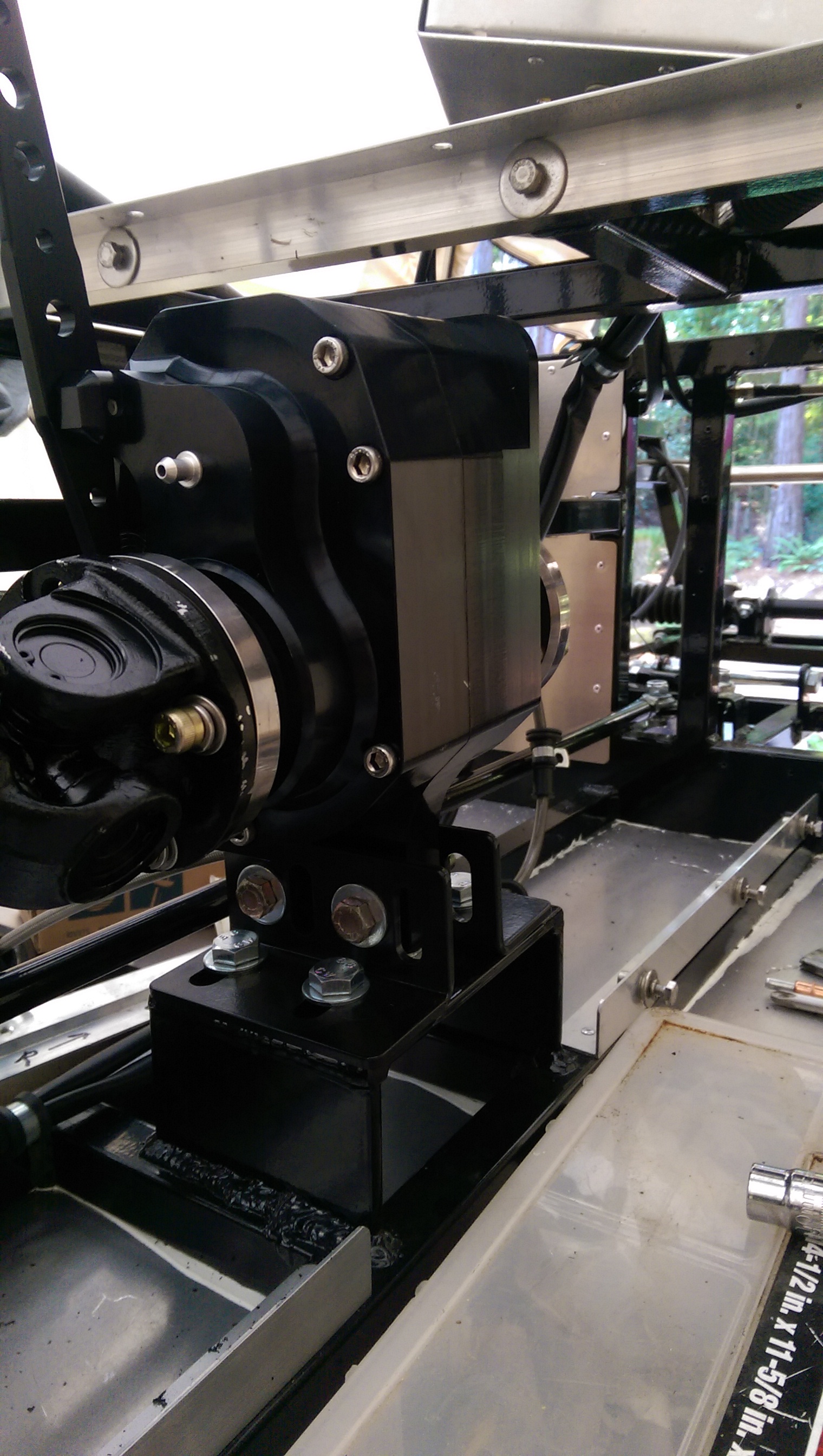
In the name of progress, the rear swingarm and driveshaft are fitted – as this gives me what I need for sizing rear shocks, and fitting a parking brake caliper (motorcycles don’t have them, generally).
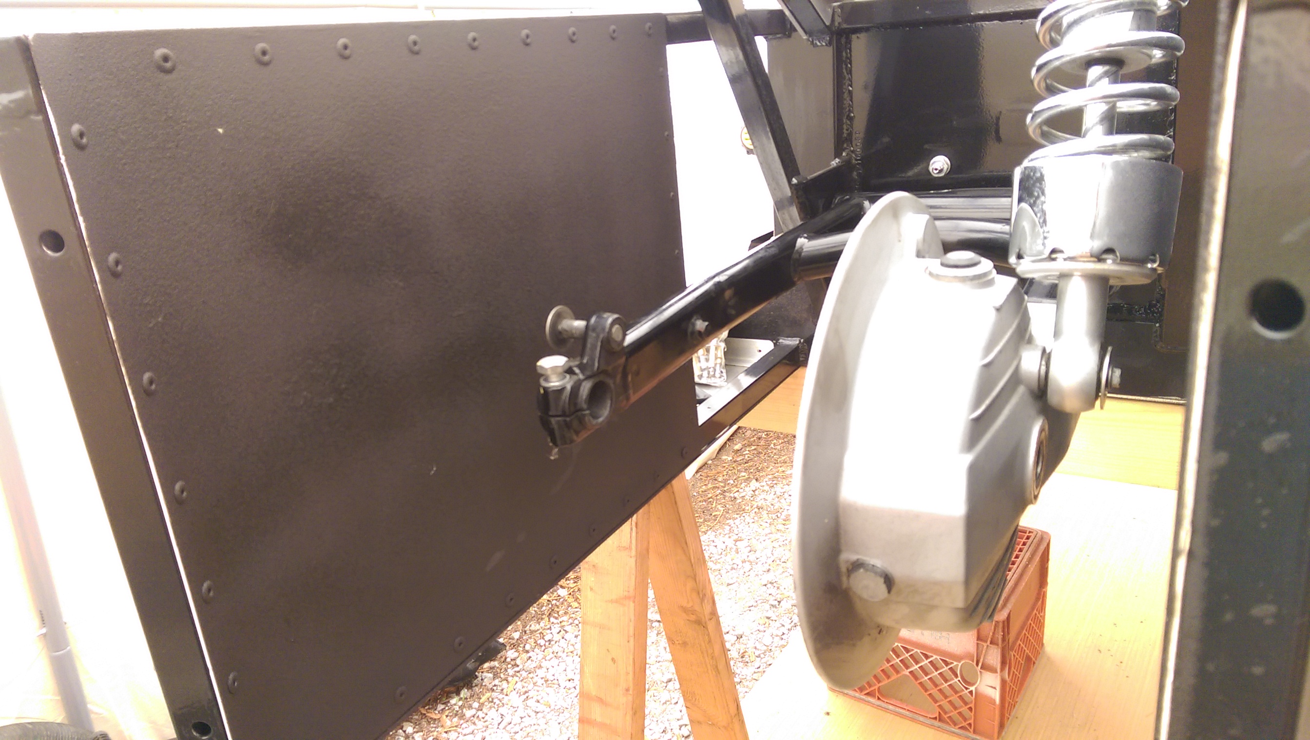
My build uses a 2003 Cal EV chassis, and the rear swingarm is longer and uses different style pivots. Thankfully, older pivot pins (gold nut, center left) are still available new from your MG dealer. Interestingly, the new pins themselves were 0.05mm larger in diameter than the originals, causing interference fit. Swingarm bearings are ball bearings, and they don’t like side loading. Further, I could try to shrink the pins (freezer) to get them to fit, but once in, they won’t come out. So a quick spin on the lathe with some emery paper, and we gently dropped the diameters of the pins the requisite amount – et voila.
The interior footwell/bulkhead panels were drilled and removed, and outward faces painted (that’s the riveted panel in the background) – the interior surface will have sound deadening foam and possibly carpet applied. Getting these panels in and out necessitates lifting the electrical box up and out of the way (box at angle top of photo) – tricky tho given the wiring is already in.
Also, fitted the driveshaft and reversing gearbox – 5 speeds forward, 5 speeds backwards.
Feels like progress.
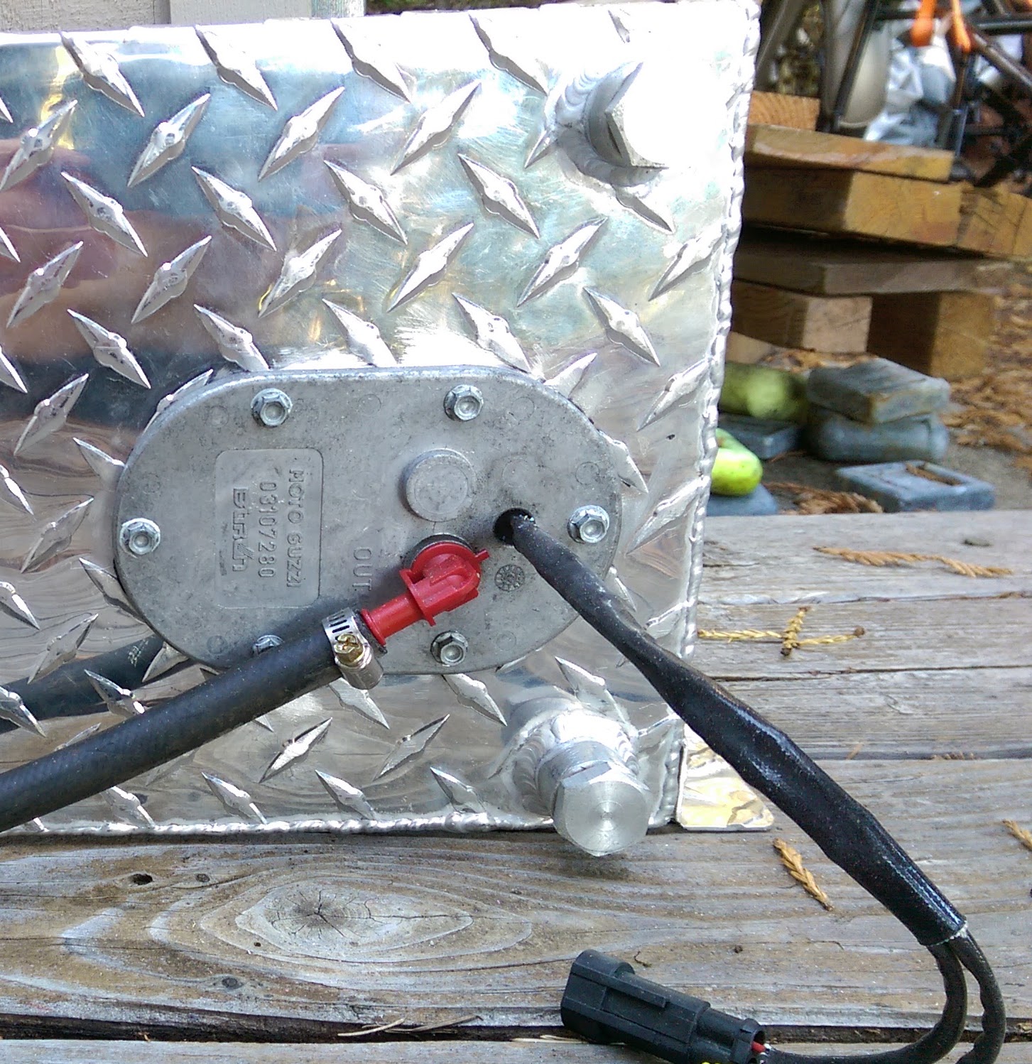
The donor bike is fuel injected, and in 2003 they had an in-tank fuel pump arrangement (1).
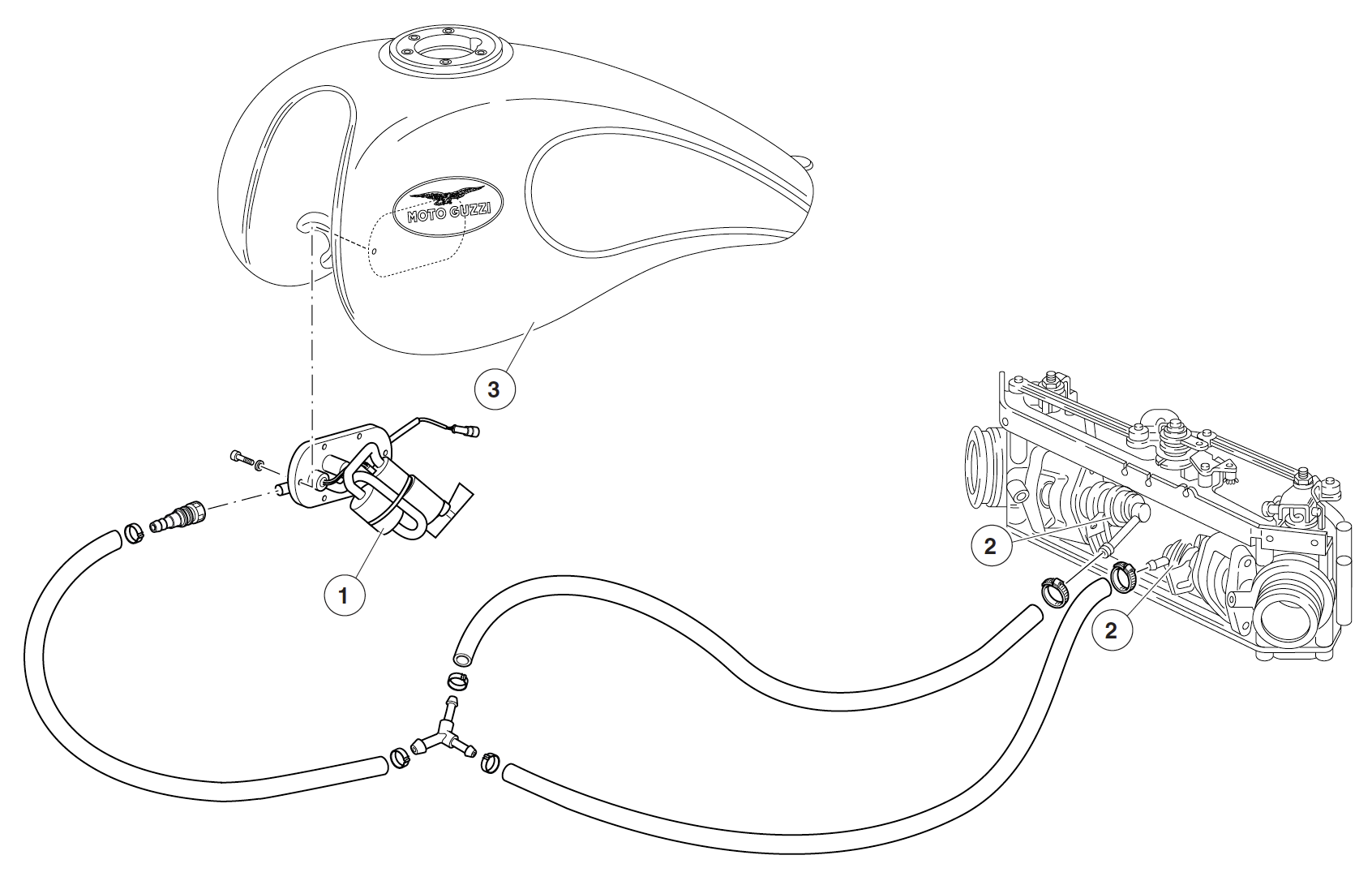
In-tank has a number of advantages, the pump is surrounded by liquid so it can stay cooler, it has an integral fuel pressure regulator so no return line, it’s got an integrated screen filter, and fuel-low light sensor.
So, the decision was to plumb this entirely externally, lose the fuel level sensor, and add an external regulator (what could go wrong??) – or, mount the pump in the tank of the trike which involves cutting a huge hole in the side of an other wise sealed fuel tank, and trying to get a pump to seal on diamond-plate aluminum.
We’re going in-tank.
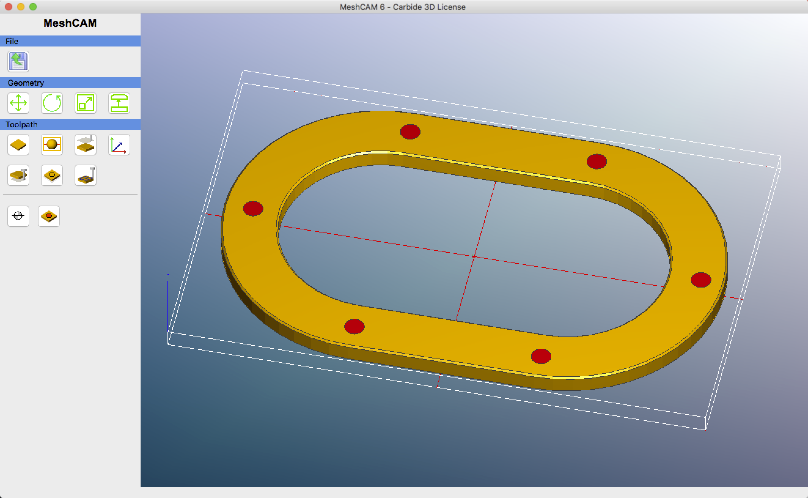
First step, a bit of CAD/CAM and some CNC work produced a “nut plate”, or a plate to put behind the opening. This will have matching holes, and be threaded to give the bolts a flat surface to clamp against, and give the bolts enough thread to torque. Metal is 6061-T6.
Then, using this as a template, cut a big hole in the side of the tank. Sorry, no photos of that step. Then, with a grinder, flatten down the diamonds to give a flat surface facing the pump. That, plus some RTV and a new gasket should do it.
Et voila, the finished article – and this has fuel in it, sitting outside on a hot day. If it’s not leaking now, it’s not going to leak for quite some time.